- Nielsen Enterprises
- Software
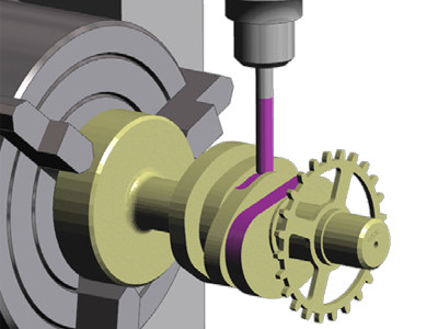
- Surfcam Milling
Testimonals
SURFCAM is powerful yet easy to learn and very user friendly.
Michael Schuffert - RKS Designs, Inc.
What used to take two and a half hours with our previous, non-SURFCAM verification product, now takes under five minutes. The images are sharp and clean. The speed and accuracy enable us to have an increased sense of confidence when cutting.
Ian Adie - Western Industrial Tooling
Surfcam Standard Features - Included in all levels
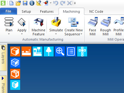
Fully Customizable User Interface
The interface can be fully customized. Command icons can be added, re-ordered and/or removed from the command ribbons, including custom macros and third party commands. Appearance of the command icons can also be edited using your own custom images. All the dialogs can be customized by creating a unique dialog mask. Once the interface has been customized as desired, it can be saved as a “Theme” and shared between other SURFCAM systems.
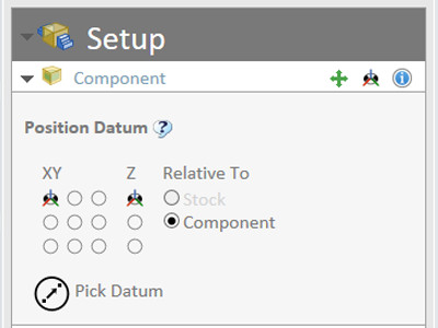
Interactive Compononent Positioning
When opening CAD data the Component Setup Manager examines the part and determines whether the part is best suited for Milling or Turning and brings you into the appropriate setup environment by default. Components are oriented to best fit on a machine tool. Changes can be made to this initial setup with interactive graphical display.
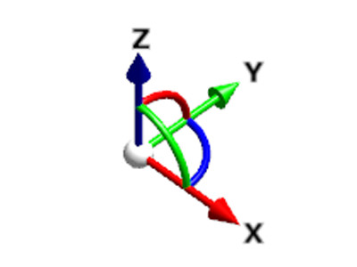
Dynamic CPL’s (Construction Planes)
Creation of construction planes include standard orthogonal planes plus the ability to dynamically drop a construction plane onto an edge or surface of a part and then dynamically drag or rotate it into position for a simplified plane creation.
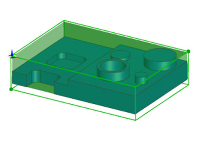
Intuitive Stock
Graphical Stock representation is fully supported and remaining stock is managed throughout the manufacturing process. Stock generation can begin from a user library of standard shapes, a geometric envelope, or imported from a base design such as a forging or casting file.
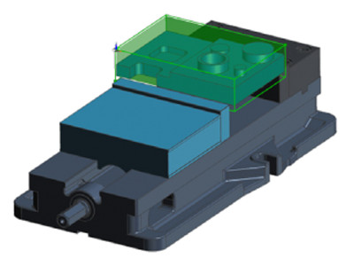
Full Support of Fixtures
Graphical support of fixtures from your fixture library, dynamically fitted to your stock. For example, when inserting a vice, the jaws are stock aware and clamp to the outer edge of the initial stock. Full collision avoidance of fixtures and clamps is supported.
2D Wireframe Design
An array of drafting tools is available for creating wireframe geometry for use in simple 2 Axis programming or to provide graphical representations for fixtures or profiles.
EWS Solid Design
Workflow Solids is included for all systems currently under maintenance. While not intended to rival production solid modelers, EWS provides the basics required for simple prismatic parts and fixtures.
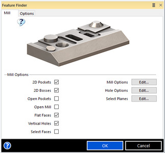
Automatic Feature Recognition
Feature Finder uses automatic feature recognition to interrogate selected portions of the active model to quickly identify machineable features including detailed hole and thread data.
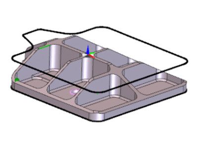
Manual Feature Finding
When your geometry doesn’t fall into one of the graphics representations directly detected as a feature, you can instruct the system to label a collection of geometry as a feature. While machining on features is not required, the construction of a manual feature can be helpful when multiple operations will be performed on a set of geometry.
Wireframe Geometry from Solids
If additional construction is required, or you want to use part of a solid to define additional fixtures or reference geometry, the underlying surfaces and wireframe geometry from the solid can be easily extracted.
Collision Checking
Collision checking of stock, fixture, and components not involved in the machining operation. Machine collision avoidance during post processing and simulation to ensure that moving tools (including those not involved in active machining) do not collide with non-moving parts.
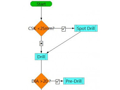
Strategy Manager
User-definable knowledge based machining automation using a flow chart decision-making process. The System recognizes manufacturing features and data from a 3D solid model and applies proven manufacturing toolpaths and techniques based on available tooling and the active machine to streamline the programming process. Easily alter or create, edit and run strategies automatically based on your own tooling and manufacturing requirements.
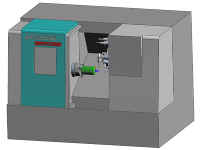
Full Machine Tool Simulation
Machine Simulation is an integral component of the post processor; it offers full simulation of the machine tool and machining process. Detects collisions between part, machine components, and tooling.